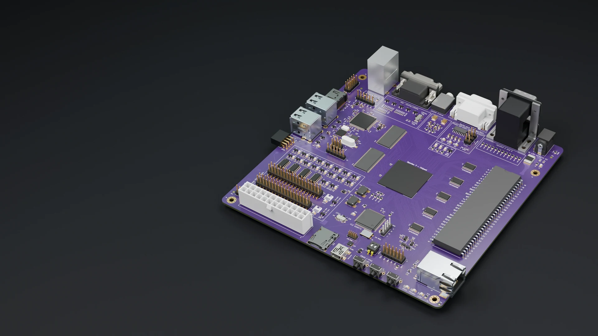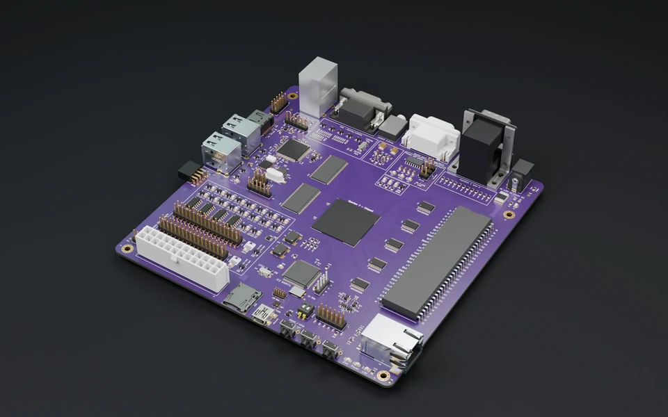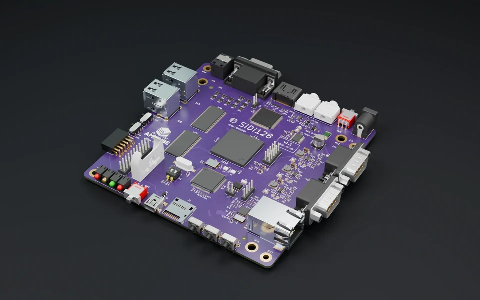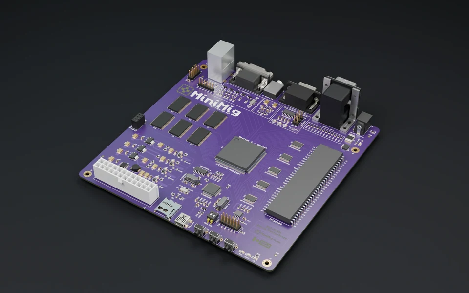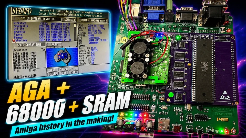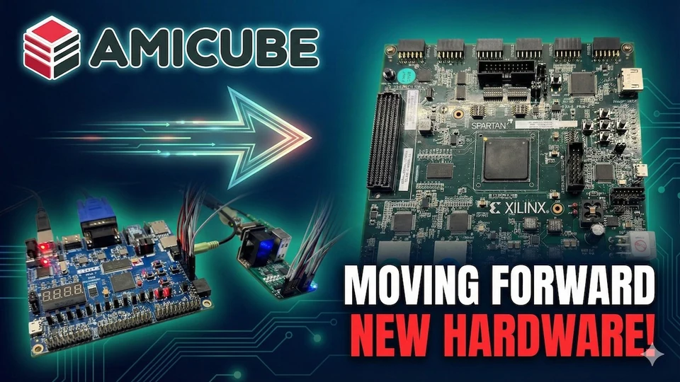
AmiCube v1.1 brings more of the Amiga experience into one hands-on computer: AGA graphics, original floppy disks, a soft 020 and a socket for a real CPU.
The Spartan-6 FPGA and 128 MiB of SDRAM give the chipset, CPU and Picasso96 RTG room to work. Choose the soft-CPU core, or explore the physical 68000 and supported accelerator path. The 18-bit RGB DAC connects that work to a real display.
The redesigned ARM F12 menu adds blank ADF creation and brings real and virtual floppy drives into the same workflow. Retained SRAM, FPGA status LEDs and new clock sources keep the board useful on the development bench, too.
Classic connections remain part of the experience: PS/2 keyboard and mouse, DB9 joysticks, analogue video and two physical floppy ports. The soft-core memory profile offers 2 MiB Chip and 120 MiB Fast RAM.
AmiCube brings the Minimig foundation into AGA, SDRAM and two distinct CPU configurations. Here is what changes from the original board.
01 / GRAPHICS
AGA in FPGA logic
OCS/ECS heritage, AGA capability, an 18-bit RGB DAC and Picasso96 RTG in supported core configurations.
02 / MEMORY
128 MiB SDRAM
The SOFT profile offers 2 MiB Chip and 120 MiB Fast RAM, plus selectable Slow RAM. Memory maps depend on the core and CPU.
03 / CPU CHOICE
Soft 020 or a real socket
Use the TG68 SOFT core, or a separate HARD core for the DIP64 CPU interface. Real 68SEC000, TF534 and PiStorm paths have board-test records.
04 / FLOPPY
Real drives + ADFs
Choose real or ADF independently for DF0 and DF1. DF2 and DF3 remain virtual. Physical-disk and ADF-to-disk copying have been demonstrated.
05 / NEW FIRMWARE
Create empty ADF
V11R1FA adds an F12 action that creates an unformatted 880 KiB image on SD. Name it, select it in a drive, then format or copy in AmigaOS.
06 / FAMILIAR CONNECTIONS
Made to be connected
PS/2 keyboard and mouse, DB9 joysticks, analogue audio and VGA, with SD storage and two physical floppy connectors.
Built for the curious
More than a new core.
SPARTAN-6 XC6SLX100
101,261 logic cells
4,824 Kbit of FPGA block RAM and 180 DSP48A1 slices provide resources for the chipset, CPU and supporting logic.
BOARD DEVELOPMENT
SRAM, clocks & status LEDs
Six SRAM devices remain for development and auxiliary RAM uses. New 27 MHz main and 12 MHz development oscillators join visible FPGA configuration/status LEDs.
SOCKET & CHIP RAM
68000, TF cards & a wider path
32-bit Chip RAM access in the FPGA; TF030-family experimentation with a documented TF534 result. Selected socket clocks up to 60 MHz have configuration-specific board records.
AGA games compiled for 68000 can run on a suitable HARD-core setup; software requiring 020+ still needs that CPU capability. The physical SDRAM bus is 16-bit. Socket-clock results depend on the CPU, adapter and core.
Real floppies are integrated into both SOFT and HARD CPU variants, with two-drive activity LEDs. Workflows include reading original disks, real-to-real copying and transfers between ADF images and real drives.
TG68 soft 020, or separate HARD core for the DIP64 socket
System control
PIC controller and image-selection OSD
Physical ARM + unified F12 menu + Create empty ADF
Floppy workflow
ADF images on flash media
Real DF0/DF1 or ADF; virtual DF2/DF3; physical copying
Graphics expansion
Native Amiga video
Native AGA plus Picasso96 RTG in supported configurations
The comparison is with the original 2 MB Minimig design. Later Minimig revisions and ARM upgrades added their own capabilities. The 18-bit DAC is the board’s physical RGB output precision; it is separate from AGA palette and RTG pixel formats.
I designed the socket path to make room for real hardware experiments as well as the soft CPU. Here are the TF534/68030 and PiStorm68K configurations, plus a closer look at the AmiCube motherboard from underneath.
AmiCube with a TF534 / 68030The physical CPU socket gives me another development path: a real 68030 accelerator alongside the FPGA chipset.AmiCube with PiStorm68KThe PiStorm68K board and Raspberry Pi connect through the socket path, while AmiCube provides the Amiga hardware and display.AmiCube, from underneathThe underside of my AmiCube motherboard, showing the power circuitry, FPGA and ARM decoupling, and signal routing.
The new ARM F12 experience
From a blank ADF to a real floppy.
I’ve brought the machine’s everyday controls into one redesigned menu: CPU, chipset, RAM, ADFs, hardfiles and RTG. Press F12 while using native Amiga video or Workbench in RTG; the physical ARM controller handles the same familiar setup on both SOFT and HARD cores.
With V11R1FA, I added Create empty ADF. Enter a 1–8-character name and the firmware writes an unformatted 880 KiB image to the SD card. Pick it in a virtual drive, then format it in AmigaOS or use it as the destination for a copy.
DF0 and DF1 can each use a real mechanism or an ADF; DF2 and DF3 remain image drives. I’ve kept reset-sensitive choices staged until you explicitly reset, so browsing the settings does not keep rebooting the Amiga.
AmiCube · F12 / Drive controls
DF0:Real drive
DF1:ADF image
DF2: / DF3:ADF images
Create empty ADF↵
Name:MYDISK.ADF
880 KiB · unformatted
Choose image, then format in AmigaOS
Illustrated F12 control summary, not a firmware screenshot.
01 / CREATEPress F12
Choose “Create empty ADF” and enter a short name.
02 / SAVE880 KiB on SD
The ARM creates an empty .ADF in the card’s root folder.
03 / INSERTPick your drive
Use the DFx image picker to mount the new file.
04 / USEFormat or copy
Format in AmigaOS, or use it as a disk-copy destination.
More than a disk picker. Native-video filters, scanlines and persistent autofire are available here too. Live display and input controls can take effect immediately; CPU, memory and drive ownership wait for reset.
Hardfiles as well as floppies. The ARM firmware handles HDF selection and supported whole-card or partition-backed storage. The selected core and CPU determine which memory and acceleration options apply.
Your image stays yours to set up. Creating an ADF does not format or mount it automatically. I’ve kept those steps explicit, so you choose which drive receives the new disk and what goes on it.
From the hardware bench
Building AmiCube, one working milestone at a time.
I’m Ranko, the maker behind AmiCube. These are the photographs and screen captures from my development bench: first boots, original disks, faster memory, stubborn bugs and the fixes that brought the machine together. I’m building on the Minimig, TG68, MiST and Edge foundations, bringing the hardware, FPGA integration and ARM firmware into one computer.
30 August 2026
Making room for 120 MiB of Fast RAM
An early rejected memory-map test, not the working memory configuration.
I wanted the new SDRAM to be useful to the Amiga, not simply present on the board. That meant getting both memory ranks, AutoConfig and optional Slow RAM working together. This early diagnostic caught an incorrect final memory descriptor and failed RAM checks. I kept the working candidate safe, rejected this result and continued toward the 2 MiB Chip + 120 MiB Fast profile.
31 August 2026
Workbench comes to life in RTG
Workbench 3.2 on the earlier SOFT-core RTG configuration.
Getting a picture was only the beginning. I worked through a black-screen problem and the hand-off between SDRAM and the display until the Picasso96 framebuffer could show a live Workbench without losing VGA output. Then I brought the redesigned F12 overlay into that same display path. The physical ARM still runs the menu; the FPGA supplies the Amiga and its graphics.
31 August 2026
Seeing what the soft 020 could do
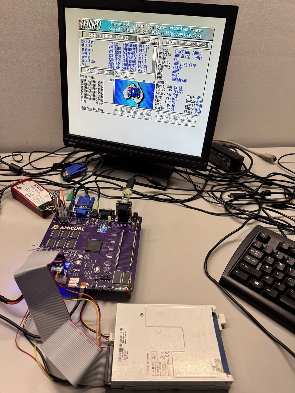
Historical accelerated profile: 10.86 MIPS; Chip Speed 14.22× an A600 in SysInfo.
The cache and direct SDRAM path gave me a much bigger playground than the original Minimig memory system. This early SysInfo screen recorded 10.86 MIPS and a 14.22× A600 Chip Speed result with the instruction cache enabled. It is a snapshot of that setup, not a promised score for every core. Keeping the faster paths compatible with floppy, chipset and display traffic mattered just as much.
31 August 2026
Bringing the real-drive controller into the system
The integrated real-drive controller boots to SysInfo; physical media testing followed.
I brought the real-floppy controller into the full system with 2 MiB Chip, 120 MiB Fast, RTG, hardfiles and the ARM menu still in place. Reaching SysInfo on the actual board was an important integration checkpoint. I treated booting and reading a disk as separate tests: a healthy desktop was encouraging, but it did not yet prove that the new floppy path could read or write reliably.
31 August 2026
The copy that stopped at cylinder 40
An early ADF-to-real-disk test exposed a repeatable cylinder-40 verification fault.
After fixing the ARM-side disk encoder, I could copy from an ADF to a real drive—but verification started failing at cylinder 40. That very specific boundary gave me a useful clue about write precompensation and the physical disk timing. I kept this photograph as a record of the problem and continued testing with expendable disks. Original disks stayed write-protected throughout the read tests.
1 September 2026
Two real drives. One complete X-Copy.
The first complete physical DF0 → DF1 copy on the integrated SDRAM/RTG platform.
This was the moment the two floppy connectors became a practical disk-copying setup. I completed a direct DF0-to-DF1 copy across all 80 cylinders and both sides, with the SDRAM, cache, RTG and physical ARM running together. The unified P112 setup also passed an ADF-to-physical-drive copy. Real and virtual disks were finally part of one workflow, with separate drive choices and activity LEDs.
1 September 2026
An original Jurassic Park disk loads
Original, write-protected floppy media reaches the game’s language-selection screen.
I put an authentic, write-protected Jurassic Park floppy in the drive and watched AmiCube reach the language-selection screen. This was the real board reading the original disk through the P112 data separator—not a prepared ADF. Alongside the copying tests, it brought the CPU, chipset, memory and physical media together in one working system. Reading the disks already on the shelf was always a big part of the point.
2–3 September 2026
Faster storage, then the work to make it dependable
Read-speed evidence only: 2,184,533 bytes/s. This early build was rejected for unsafe writes.
My first Fast-IDE integration reached 2,184,533 bytes per second in SysInfo, but the photograph also records a damaged filesystem. I rejected that build and worked on the write path and the floppy-copy regressions. The later R6 work restored physical copying in Normal and Fast modes; I then integrated seven reviewed AGA corrections and a RAM-ready handshake change. The fast number was a checkpoint, not the finish line.
6–8 September 2026
Tuning speed without losing the working machine
6 September comparison: 7.27 MIPS and 9.46× Chip Speed on the protected cost008 build.
I compared the newer working core with the earlier performance screen to understand what had changed in the CPU-to-memory handshake. This cost008 test recorded 7.27 MIPS and 9.46× A600 Chip Speed; the older screenshot was not an identical-settings comparison. I kept checking Workbench, floppy operation and SysInfo as the work continued. On 8 September I selected LQ42 as the working SOFT release and retained the earlier rollback.
9 September 2026
PiStorm reaches AmiCube’s own RTG output
HARD H8 with PiStorm: 800 × 600, 16-bit colour through AmiCube’s display output.
After getting PiStorm, PiStorm68K and a physical 68SEC000 booting on the socket path, I worked on storage and graphics. H7 reached a reported 2,184 KB/s in the tested 60 MHz socket configuration. With H8, I then ran Workbench through AmiCube’s own Picasso96 RTG output using the driver from the soft-020 setup. The screen shows 800 × 600 at 65,536 colours—not the Raspberry Pi’s HDMI output.
What I’m working on next
The soft CPU and physical socket now have separate core builds, sharing the same physical ARM controller. I added empty ADF creation in V11R1FA, and the next socket experiment, H9 with ARM V11R1FC, is testing reset-applied Turbo Chip and Kick Turbo controls. It is a development test, not a replacement for the working release. I’m continuing compatibility, storage and timing checks while keeping the tested configurations recoverable.
Photos show the configurations and dates described, including early rejected tests. Benchmark results are configuration-specific. LQ42 remains the board-tested SOFT release; socket development and global timing qualification continue. Use write-protected originals for reading and spare media for write tests.
WoRC EXPO 2026 · PLATINUM SPONSORMeet us in Waterloo, September 12–13.
The product sections below stay connected to WooCommerce, so pricing, stock, gallery images, summaries, and add-to-cart controls continue to come from the product records.
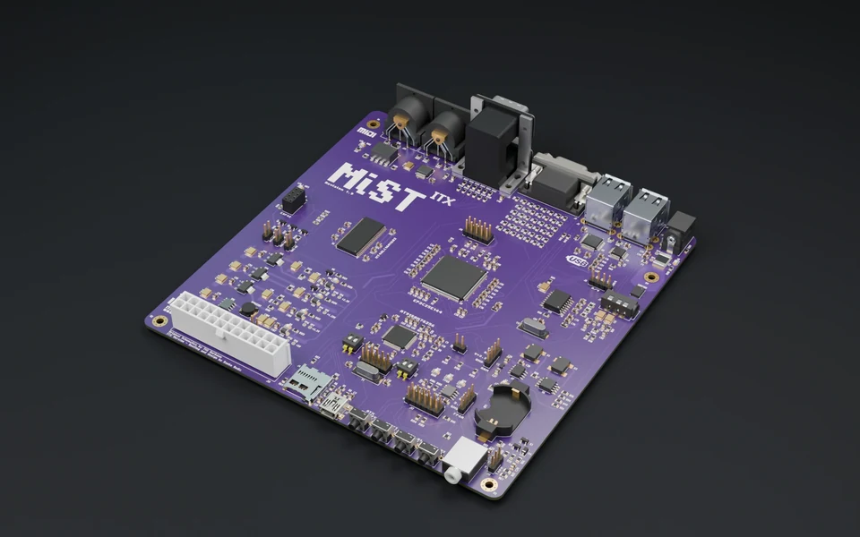
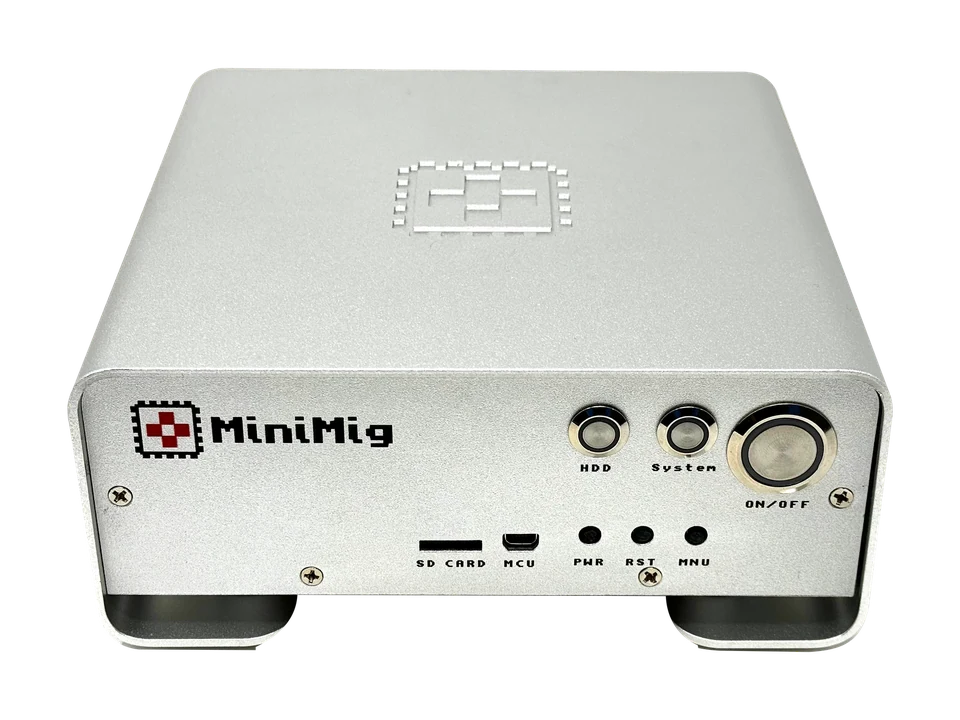
Minimig v1.98itx 6MB with original case is a 2024 Mini-ITX Minimig board with a 6-layer ENIG PCB, real MC68SEC000 CPU, 6 MB RAM, OCS/ECS FPGA core with MIA BootROM replacement, +5V DC-DC regulation, resettable fuse protection, SBRT Schottky protection, SN74CBTD level shifting, power rail LEDs, VGA output, PS/2 keyboard/mouse support, improved FastSPI, PiStorm kick.rom caching support, and tested accelerator support including TF030 at 50 MHz. Includes 16 GB SD card, +12V 4A power supply, and original anodized aluminum case.
The Minimig v1.98itx 6MB Purple ENIG is a Mini-ITX Minimig board with a 6-layer ENIG PCB, MC68SEC000 CPU support, 6 MB RAM, improved power regulation, resettable fuse protection, rail LEDs, SN74CBTD level shifting, FastSPI improvements, and the updated OCS/ECS core with MIA BootROM replacement. Includes board, 16 GB SD card with Minimig FPGA core, MC68SEC000 CPU, and +12 V 4 A universal power supply.
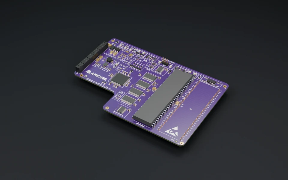
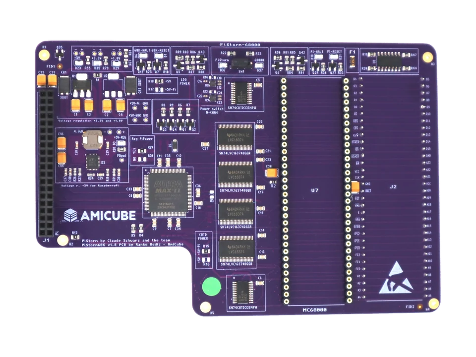
The PiStorm68K v1.8 by AmiCube is a special edition 6-layer ENIG PiStorm accelerator board for Minimig and 68000-based retro systems. It lets you switch between Raspberry Pi-based 68000 CPU emulation and a real Motorola 68000 CPU using an onboard selector, with electronic CPU power switching, CPU/power rail LEDs, LTC3119IUFD +5 V regulation, SBRT10U50SP5-13 rail protection, resettable fuse protection, and improved decoupling. Raspberry Pi and MC68000 CPU are not included.
3D printed PiStorm68K case by AmiCube, made with galaxy filament for a dark metallic finish. Designed for presentation, board protection, bench display, and AmiCube-branded PiStorm68K showcases.
Board not included. This listing is for the 3D printed case / presentation accessory only.
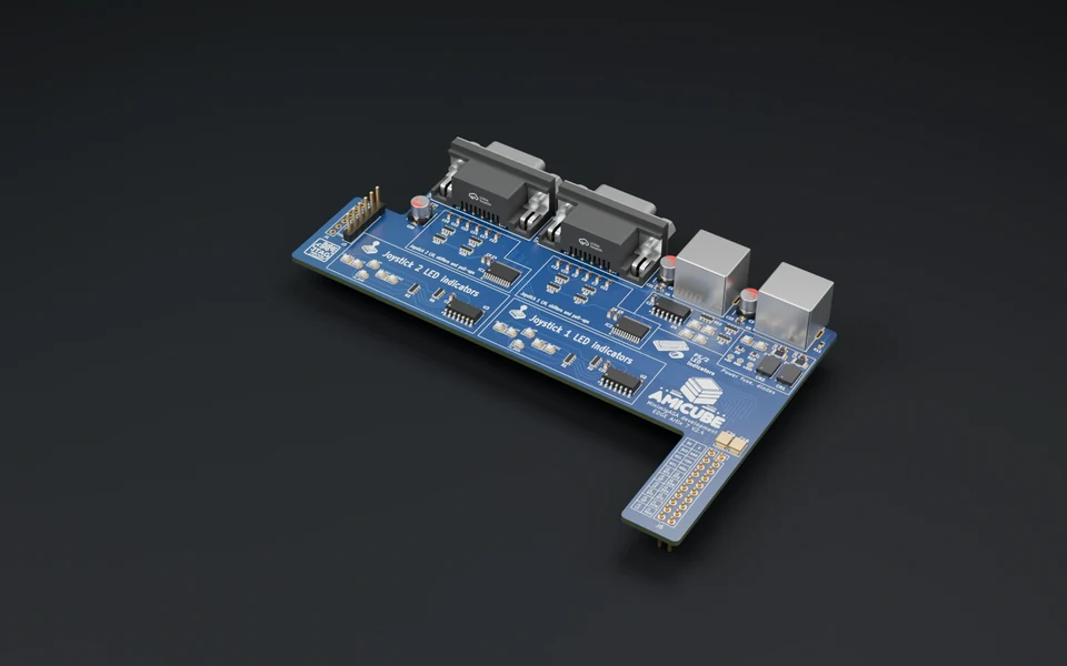
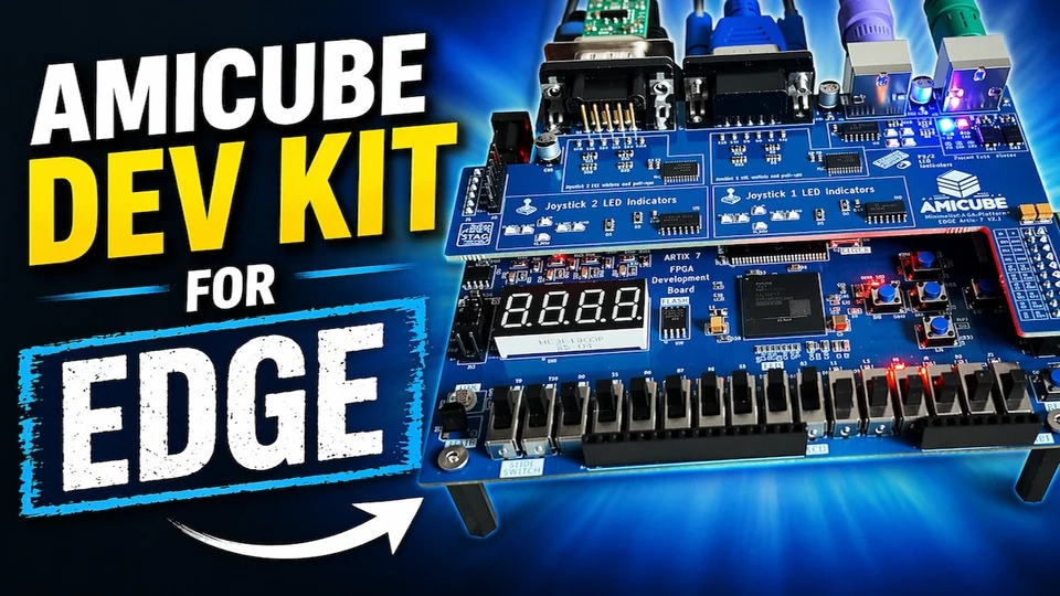
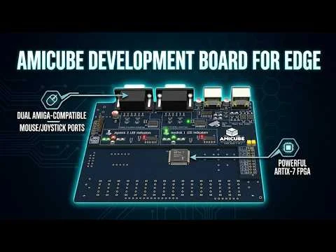
The AmiCube DEV1 is a dedicated I/O and development board for the low-cost Edge Artix-7 FPGA platform. It is designed for testing the AmiCube Minimig AGA core with real DB9 joystick ports, PS/2 keyboard and mouse support, HDMI/VGA output paths, protected 3.3 V and 5 V rails, true level shifting, and bundled digital core/scripts/documentation. Edge FPGA baseboard is not included.
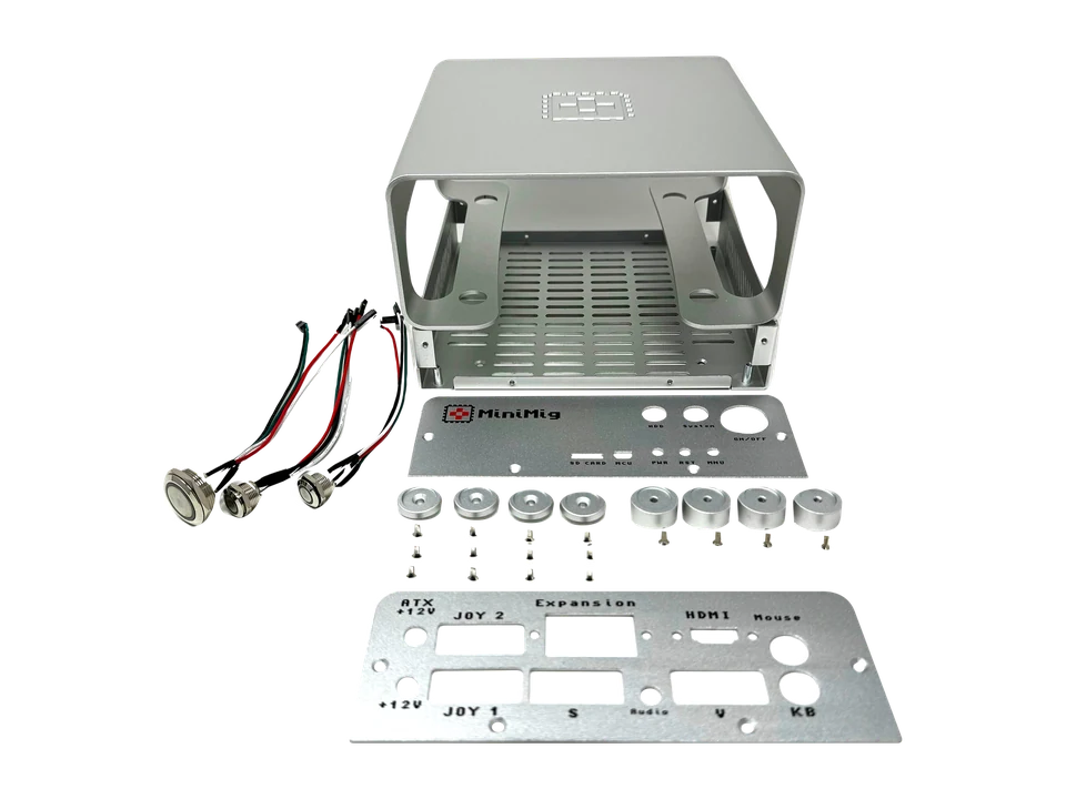
The Original case for Minimig v1.9X ITX MARK-II is an anodized aluminum enclosure made for compatible Minimig v1.9X ITX boards. It includes the case assembly only, with 3D printed/internal components and LED button styling as applicable. Minimig board, power supply, cables, and accessories are not included unless specifically stated.
Boards are assembled with repeatable tools: stencil printing, pick-and-place, reflow, inspection, and stocked components for ongoing Minimig and AmiCube production.
AmiCube
Kayo pick and place
Thanks to advance PnP machine we can produce 50 boards per day! In addition we have spare components in stock.
AmiCube
Stencil Precise stencil printer
SMT stencil printer is perfect addition to any assembly line. Every Minimig we produce has precise amount of solder paste.
AmiCube
Reflow oven
Using Neoden IN-6 we can produce as many boards as needed. Profile is selected based on Minimig board characteristics.
Do you have any questions about our products?
Then do not hesitate to contact us. Our support team will be happy to answer your question. Usually within one to two working days.